Chapter 1: Unit system and the trench grid
Setup

In this lesson we'll learn how to use the software AutoCAD to redraw an archaeological excavation plan. We will talk about the system of units and create a 10x10 metre grid that can be printed out at a scale of 1:50, i.e. as a 20x20 centimetre grid on real paper.
First we need to make sure that our software uses the metric system. We can do this by opening a template from AutoCAD, which you can find on the home page under the Start a new drawing (**Zeichnung starten**) box. If you open the drop down menu you'll find a template called acadiso.dwt. Click on it and AutoCAD will open a new blank drawing.
What you see now is what we call the drawing space (**Modell**), where we will do our drawing. In it we will draw 1:1, which means that if we need a 1 metre long line, we will draw a 1 metre long line in the drawing space. Later we can create layouts where we can specify what we want to print from the drawing space and at what scale. AutoCAD works in millimetres by default, so to draw a line 1 metre long we would have to draw 1000 units. We can change this if we wish, but more on this later.
Scales
First, let's talk about scale. If you already know what 1:50 scale is, you can skip this chapter and go on to the next. What does it mean to draw at 1:50? It basically means that your drawing is 50 times smaller than the original. So a 50 centimetre line in the real world would only be 1 centimetre in your drawing. On the other hand, if you were to draw 1:20, the 50 centimetre line would be 2.5 centimetres, so the final drawing would be larger. If you were drawing 1:1, 50 centimetres in the real world would be 50 centimetres on paper.
It is obvious why we use scales, because trenches of 10 x 10 metres would not fit on normal drawing sheets. On an excavation, you always draw to scale, and rescaling the drawing (for example, for publication) is always difficult. Not so with a digital drawing, where we can easily choose between different scales and produce as many results as we want.
Exercise: Draw a 10cm line
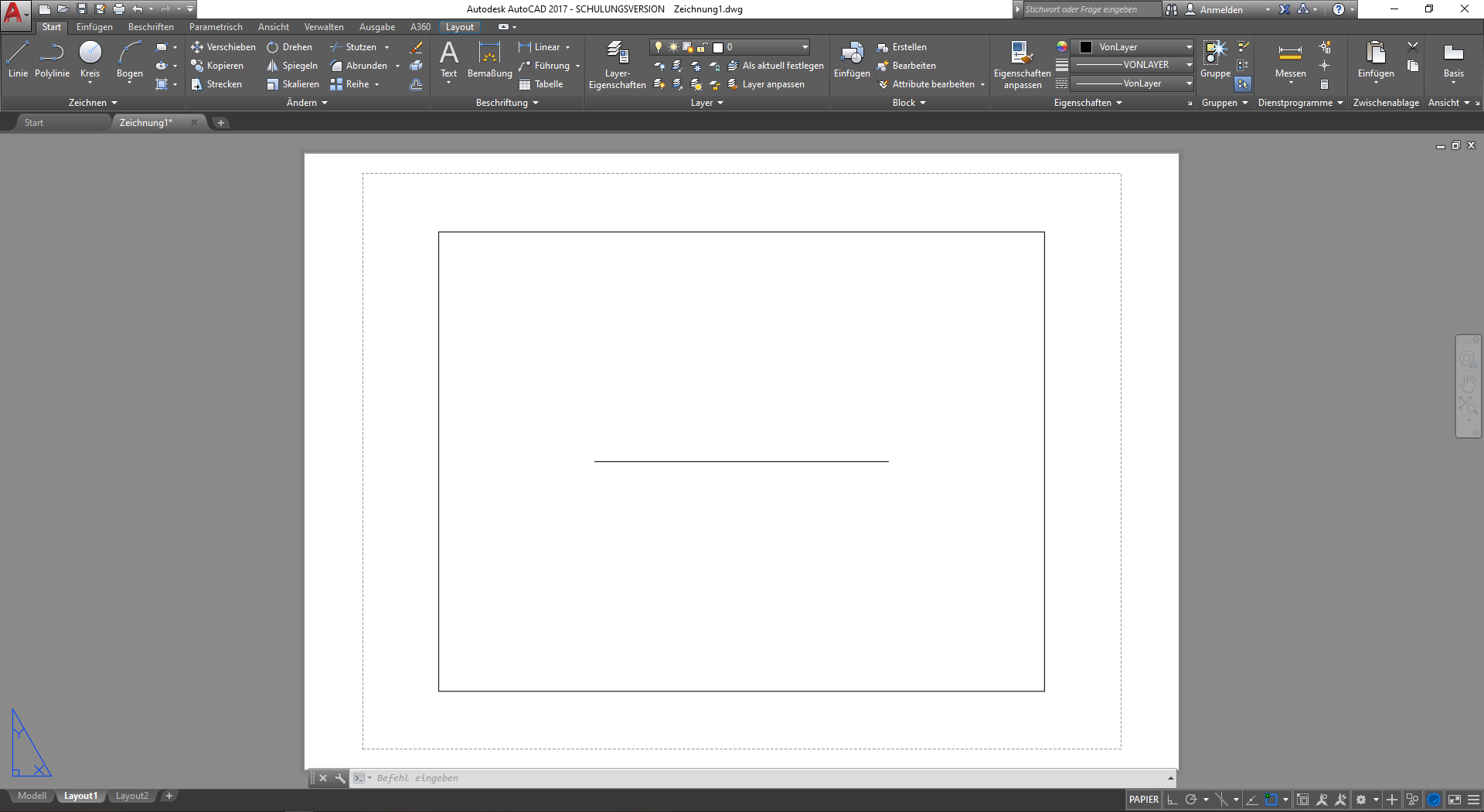
So let us do a little experiment. We want to draw a 10cm straight line in the Drawing Space. To do this we will select the Line (**Linie**) tool from the top menu and enter some coordinates ourselves. Instead of clicking somewhere in the drawing, we will enter the coordinates in the Command Line (**Befehlszeile**) at the bottom, like this: 0,0,0 for the first point and then 100,0,0 for the second point. You can quit the Line tool by pressing Space (**Leertaste**). To see the line, use the mouse wheel to zoom in and out and find the relatively small line at world origin. Zoom in on it so that you can see the line clearly.

What we have done is to draw a line 100 units to the right. When entering coordinates, we always enter X,Y,Z coordinates. Since we are only drawing in the XY axis, the Z axis will always be 0. The first point was at 0,0,0, which means the line starts at the world origin of the drawing. The second point had an X value of 100, which means we are drawing the line 100 units to the right.
If we switch to the Layout view, we will see that the line is relatively large, as ACAD's default setting needs some adjustment. First of all, we want to get rid of the grid that appears as the background of the drawing. Double click inside the drawing so that the frame border becomes thick. Then press F7 to turn off the grid. Double click outside the drawing to make the border thin again. Then select the frame border by clicking on it so that it turns blue and then right click to open the Properties. There select the View Window Size and set it to 1:1. The line is now 10cm long, you can print this page to measure its dimensions.
Change the scale
So what we've learnt from our little experiment is that if we draw 100 units in the Drawing Space, we'll get a 10cm line in the Layout at a 1:1 scale. So we can simply remember that we are drawing in millimetres when we are in the Drawing Space, because 100mm is 10cm. However, as mentioned at the beginning, a scale of 1:1 is not really practical as we will be drawing trenches that are 10x10 metres in size. We must therefore choose a smaller scale to fit our redrawing onto an A4 or A3 sheet of paper.

Let's say we want to have our layout in 1:50 scale for a trench by trench view, and in 1:100 scale for a more overview style layout. When we switch to our Layout1 we can simply change the scale as we did before. We select the frame and right click to open the Properties. There we select the View Window Scale and change it to 1:50. You'll immediately notice that the line is now much smaller. You can print out the paper and measure the line, but we can also do some calculations.
We know that our line is 10 cm long at a scale of 1:1. If we change the scale to 1:50, the line should be a fiftieth of its original size, so it should now be 0.2 cm or 2 mm long. When you print Layout1 you should see a 2mm line. To keep things tidy, we should rename our Layout1 to something like Layout 1_50 (note that a colon does not work here) by right-clicking on the tab name at the button and selecting Rename (**Umbenennen**).
We can now repeat the process with Layout2 and remove the grid inside the frame (F7), change the scale to 1:100 in Properties and rename the layout to Layout 1_100. Of course the line should shrink to a size of 1mm.
Drawing an excavation grid
Of course, instead of a simple line, we want to create a redrawing of an archaeological trench. However, before we start redrawing the excavation data, we need to prepare a grid in which we will do the redrawing. In our example, we will be working with 10x10m trenches, which means that everything we want to redraw will be within this 10x10m boundary. There are many different systems in archaeology, we just need to choose one. In our case, we want to create a 10x10m boundary with some crosses. We want to put large crosses at the corners of the trench and smaller crosses in between along the border, each cross 1m from the next. The first thing we want to do is delete the line we have just drawn. Just select it with a click and press Del (**Entf**) to delete it.
Setting up a new layer
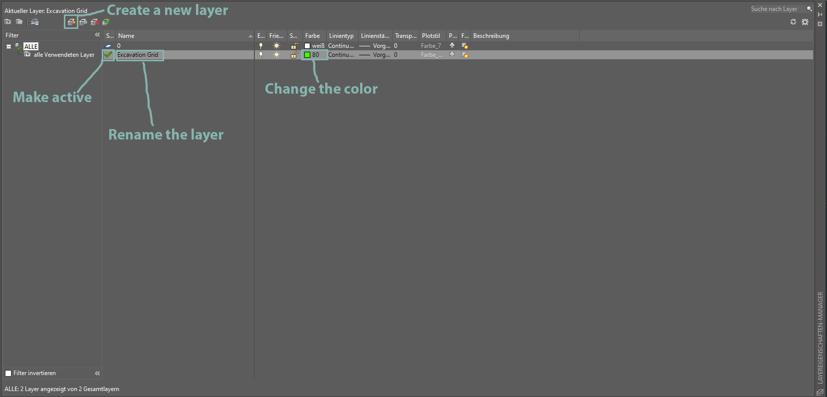
Layers are used to separate different types of content within an ACAD drawing. For example, we can assign different colours, line styles or line thicknesses to different layers and use them to differentiate between different stratigraphic units, or in this case the trench boundary. To set up a new layer, we need to open the Layer Properties (**Layer-Eigenschaften**) from the top menu. A new window should appear.

So far we only have one layer called 0, which is ACAD's default layer and can't be deleted. I don't usually end up using it. To create a new layer, press the New Layer (//Neuer Layer//) button at the top, indicated by a yellow star next to the layer icon. Give the new layer a recognisable name like Excavation Grid. We also want to change the colour of the layer by clicking on the white colour box in the corresponding row. Choose a nice light green colour. The last step is to make our new layer active, so that whatever we draw will automatically be drawn on the new layer. Do you see the green tick next to the default layer 0? This indicates that 0 is the active layer. To change this to our new layer, simply double click on its name Excavation Grid. Close the window by clicking on the little x in the top right or left corner.
Creating a cross in the right dimensions
To start with, we want to create a cross to use as the four corners of our grid. This cross will be 1cm high and 1cm wide at 1:50 scale, so we need to think for a moment. If we want to draw a 1cm line at 1:50, how long should it be at 1:1? Of course it should be 50cm long when we draw it. When we print it at 1:50 scale, it should appear as 1cm. How long will it be at 1:100? You can work that out. So to draw this line, we are going to use exact coordinates to be very precise.
To start, we will select the Line tool (**Linie**) from the Start menu at the top. Instead of drawing by hand, we will enter the coordinates in the Command Line (**Befehlszeile**) as before. The first point should be 0,0,0 and the second point 500,0,0. To make a cross we also need a vertical line from top to bottom. Try to work out the coordinates yourself before reading on.

To draw the vertical line, start at the point 250,250,0 and end at the point 250,-250,0. You should now have a perfect cross, which should print in the dimensions 1 by 1cm. Let's move the cross to the world origin by first selecting both lines. Make sure you have selected both lines, then select the Move (**Verschieben**) tool and make sure your Snapping is turned on. The corresponding icon should be highlighted in blue (see screenshot). If not, you can toggle Snapping on and off by pressing F3. With the Move tool selected and Snapping enabled, you can now snap to the centre of the cross by moving your mouse there. You should feel a snap towards the centre, indicating that you can click (just once). You can now move your cross. Instead of clicking, type the desired coordinates into the Command Line (**Befehlszeile**) -> 0,0,0. Your cross should now have moved to the world origin.
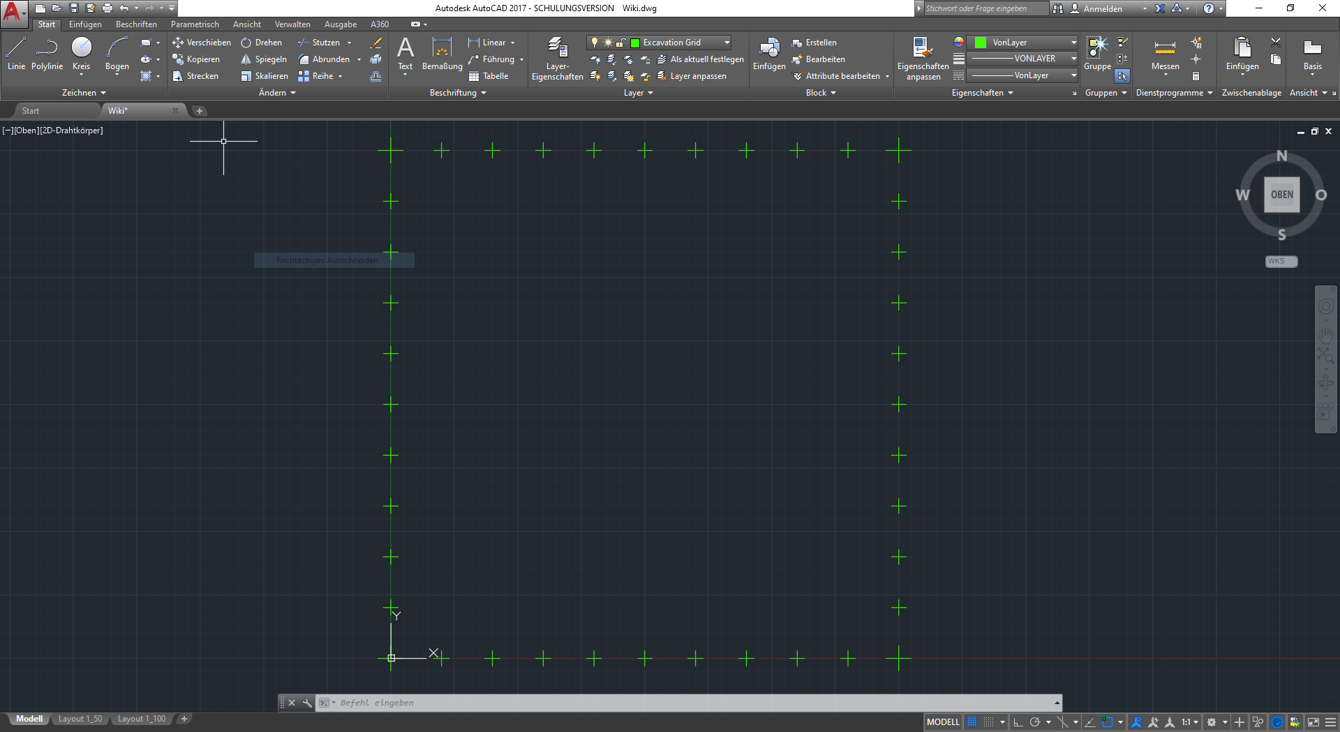
The last step should be to copy the cross to the three remaining corners. Select both lines again and this time use the Copy tool (**Kopieren**) and click again in the middle of the cross with Snapping enabled. Again we enter the target coordinates ourselves: 10000,0,0, 0,10000,0 and 10000,10000,0. You should now have a 10x10m grid on your canvas.
More crosses...
So the final step for this lesson is to create smaller crosses to fill in the gaps between the larger crosses we have just created. This time we want the smaller cross to be 0.6cm high and 0.6cm wide at a scale of 1:50, so try to work out how long we need to draw our lines to achieve this... 30 cm is the answer. So we repeat the steps we have just done for a smaller cross. Let's start with the first point at 100,100,0 and the second point at 400,100,0. The second line starts at 250,250,0 and ends at 250,-50,0.

Now we need to position the smaller cross. Again we use the same method as before: Select both lines and choose the Move (**Verschieben**) tool. Make sure Snapping is on and select the centre of the smaller cross. Now, instead of clicking, we type in the coordinate that is exactly 1m to the right of our bottom left corner. We enter the coordinates 1000,0,0 as the target. This way we have positioned the smaller cross exactly 1m to the right of our larger cross. Now we could continue like this, or we could use a little trick. Instead of entering the coordinate each time, we can save some time. First we select both lines of our smaller cross and then select the Copy (**Kopieren**) tool from the menu. First ACAD wants to know the base point. This time, instead of selecting the centre of our smaller cross, we want to select the centre of the cross to the left, which is exactly 1m away. Make sure you have Snapping enabled. As you can see, you can now make copies of the smaller cross 1m to the right of where your mouse is. Now click on the centre of the smaller cross you want to copy. You have now created a second smaller cross 1m to the right of the first smaller cross. Now click on the centre of the latest little cross and you will create a third, and so on... Continue until the bottom line is complete, so you should have eight smaller crosses between the two larger corner crosses. Now we want to copy the whole bottom row of smaller crosses to the top. Select them all (not the big ones!), choose Copy (**Kopieren**) and choose the bigger cross on the left as your base point. Copy the selection to the big cross on the top left and you should have the top row done. For the vertical lines, start again with a cross that you copy to the top of the bottom left corner and then continue to the top. Finally, copy the left column of smaller crosses to the right. Your trench boundaries should now be complete.
There is only one thing to correct. If you look at your Layout 1_50, you'll see that we can't see the whole trench on the A4 paper. As the bleed on the paper is 20cm, we are very close to the printable area of the paper. In order to see the full drawing at 1:50 scale, we need to change the paper size of Layout 1_50 from A4 to A3. To do this, right-click on the tab of Layout 1_50 and select the Page Setup Manager (**Seiteneinrichtungs-Manager**). In the pop-up window, select Layout 1_50 and click Change... (**Ändern...**). In the new window, select paper format (**Papierformat**) from the drop down menu and choose ISO A3 (297.00 x 420.00 mm). Click OK and Close (**Schließen**). You must now adjust the visible margin by selecting it and dragging a corner to the length of the paper. By double clicking on the border (the border will become thicker), you can edit the view inside by holding down the mouse wheel. Drag the trench to the centre of the paper, making sure you don't rotate the mouse wheel as this will change the scale. When you are happy, double click outside the edge to make it inactive, so that you can return to your drawing.
You can now proceed to Chapter 2: Referencing, Layers and Drawing
