Chapter 2: Referencing, Layers and Drawing
Include an excavation drawing
When we want to redraw something, we first need a drawing to refer to. Excavations produce a lot of drawings over the course of a season, and many of them are still analogue, i.e. pen and paper. In order to digitise the drawing, we first need a good scan, which then needs to be rectified so that it can be used in our digitisation. Fortunately, this has already been done for you, and you can download a JPG file to use as a reference: Trench Drawing.
To use the drawing in our ACAD file, we will first create a new Layer, so first open the Layer Properties (**Layer-Eigenschaften**) from the top menu. We can see that we have our system layer 0 and our layer Excavation Grid. We will now create a new layer with the New Layer (**Neuer Layer**) button and name it Excavation Plan. Make the layer active by double clicking on it, leave the colour white or change it to white and then close the Layer Properties (**Layer-Eigenschaften**).
To associate an image with our drawing, we will select the Insert (**Einfügen**) tab at the top right of the menu and then the Assign (**Zuordnen**) button. We search for our drawing, which ideally should be saved in the same folder as our drawing. In the new window we should make sure that the Path Type (**Pfadtyp**) is changed to Relative Path (**Relativer Pfad**) as this refers to the image file relative to the position of our ACAD drawing. If we put both the ACAD file and the image file in the same folder, we can put the whole folder on a USB drive and take it somewhere else. So press OK and the window disappears.

ACAD now wants us to choose a starting point. Choose something within the limits of the trench, but don't put it on top of the crosses. When you click once, you'll see a rectangle that you can scale. Make the rectangle fit roughly inside the green crosses of the out trench and click again. You should now see an image file in your drawing area. If you look closely at the image you should see four very faint crosses in each corner of the drawing. These crosses represent the 10x10m trench on the drawing itself. We now need to match this to our trench so that the drawing is linked to ACAD at the correct scale.
We start by positioning one of the faint crosses under one of our own green crosses. We want to move the lower left cross of the drawing under our lower left green cross of the trench. First we select our drawing by clicking on its border. The menu at the top changes automatically, so we change it back by clicking on the Start tab and selecting the Move (**Verschieben**) tool. We now need to select the point on the image file that we want to move and we need to select the centre of the lower left cross (on the image file) as accurately as possible.
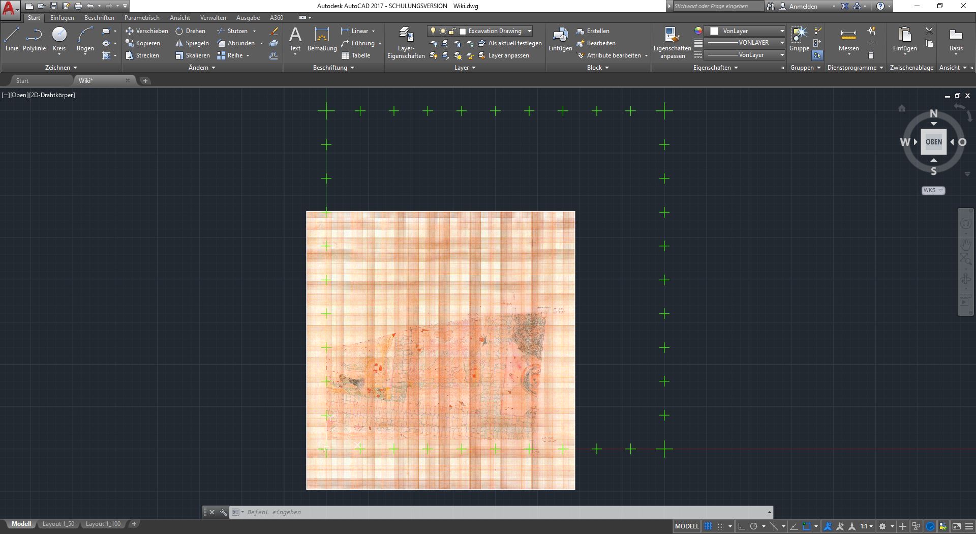
Make sure your Snapping is off by checking that the rectangle icon in the bottom right menu is grey and not blue. If you want to turn snapping on, simply press F3. You can zoom in by clicking once in the middle of the lower left cross on the image file. When you zoom out, you'll see that you can now move the image around. What we want to do is position this exactly under the lower left cross of our trench. We will now turn on Snapping (F3) and click in the middle of our green lower left cross. The only problem we have now is that the drawing is on top of the green crosses, so we need to change the order of things in our drawing. Select the image file, right click anywhere in the drawing area and select Drawing order (**Zeichnungsreihenfolge**) from the menu. From this menu select Lowest (**Ganz unten**). Now the image file is under the green crosses and as you can see the lower left cross of the image file corresponds to the lower left cross of our trench. We now need to scale the image file so that the other three crosses correspond to our green crosses in the corners.
So first we select the image file again and in the top menu change the tab back to Start. Now we select the Scale (**Skalieren**) tool. We now need to tell ACAD from which point we want to scale and we will select our zero point which we have just correlated with the image file. So, with Snapping enabled, we click once in the centre of our lower left green cross. As we do not want to scale the image by hand, we want to select another scaling mode. As you can see in the Command Line at the bottom, there is a decision to be made. What we want is Reference (**Bezug**) and we can select this either by clicking on it in the Command Line or by typing the blue highlighted letter and pressing Enter.
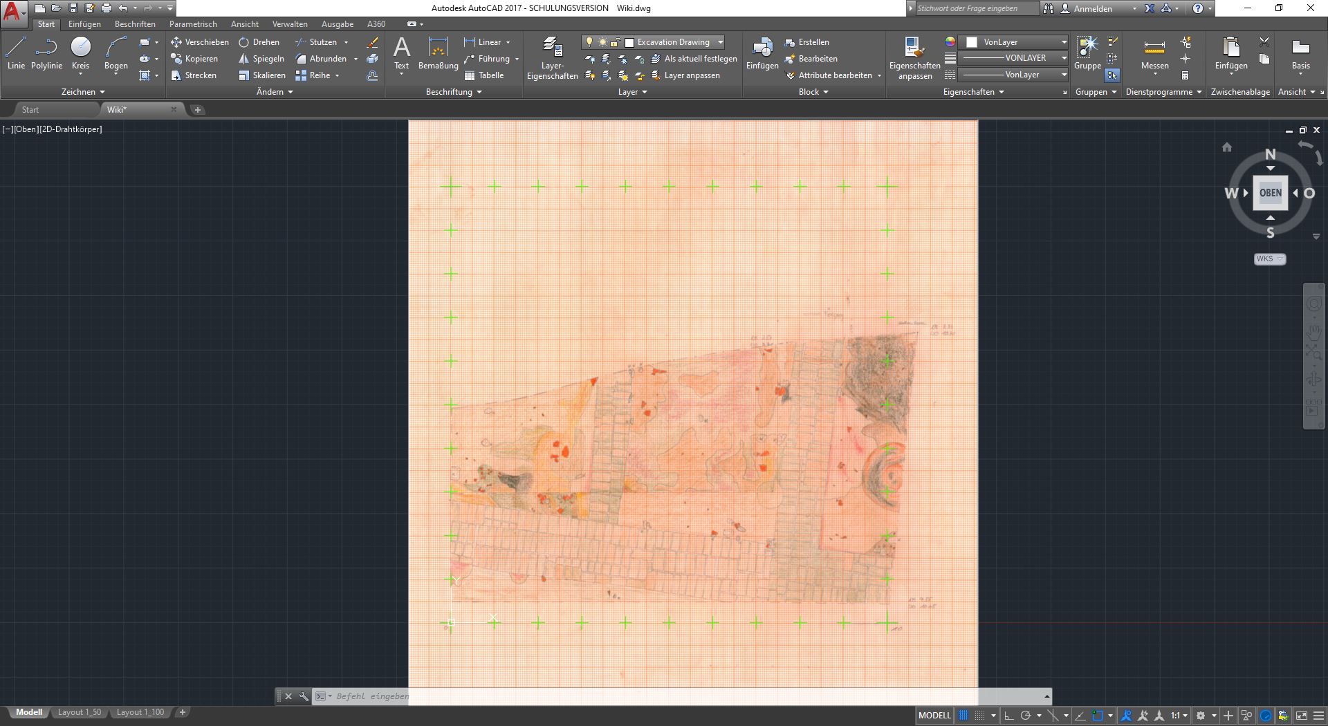
Now ACAD wants a reference length of what to scale. Basically, ACAD asks us what part of our image file we want to scale. We want to select the length between the bottom left and bottom right corner of the image file. So we first click (with Snapping enabled, because we have already positioned the lower left corner under our green cross) in the middle of the lower left corner and then (with Snapping disabled, because we don't want ACAD to jump to another point) in the middle of the lower right corner (of our image file). Also: press and hold the SHIFT key to keep the line between the two points straight.
You'll see that you can now scale the image file as much as you like. But we have a reference point we want to stretch this file into: the lower right green cross of our trench. So now turn on Snapping and click in the middle of the lower right corner of our green trench et voilà, the image file is correctly scaled! You can check all four corners, but if you have done everything correctly, the image file should sit scaled and neatly under our green excavation grid that we have already scaled in the previous lesson. The only thing I want you to change now is that we want to see the original drawing in our Drawing Space, but not in our Layouts. If you look at our two Layouts, you'll see that the original drawing is there too. So let's change that.
So first we switch to our first layout called Layout1_50 and double-click inside the frame to make it active, as indicated by the thick border. Don't move or scale anything! Open the Layer Properties (**Layer-Eigenschaften**) and select the layer for our drawing called Excavation Drawing. If you go to the right there is a column called AF Freeze (**AF Frieren**). You may need to expand the columns to see this. Click on the icon for your layer in this column. It should change from a rectangle with a yellow star to a rectangle with a snowflake. You will immediately see that the original drawing is no longer visible in our Layout. Double-click outside the frame in the layout to make it inactive and repeat the procedure for the other layout called Layout1_100.
Start drawing

Ok, let's start drawing! We open the Layer Properties (**Layer-Eigenschaften**) and create a new layer called Excavation Outline. We want to change the colour of the layer to pink by clicking on the colour box in the list. We also activate the new layer and close the properties. To draw we will use the Polyline tool (**Polylinie**) and make sure that snapping is off (F3). So, back in the Drawing Space, we start at one corner and click along the outer line of our trench. We want to follow the line as closely as possible, using only as many points as necessary. When you reach the edge of the window, you can pan the view (press the mouse wheel) while still drawing. The aim here is to circle the trench once with a polyline.
An important note: We want to think ahead, of course! As we follow the outer line of the trench, we need to be aware of intersections. What does this mean? Every time the outer line of the trench (the one we are currently digitising) crosses or touches another line (of a stone, a different colour of soil or a mud brick), we definitely create a point. This means that when we later redraw this stone (which touches our trench), we can connect the line of the stone to the point of the trench line we created earlier. This will help us a lot later on when we want to fill in the stones, earth and mud bricks with paint. When you reach the end of the line, which is basically the point where you started, make sure you turn snapping on (F3) and click the last point on the first to complete the circle. Turn snapping off again (F3).
We will continue with the mudbricks. Again, create a new layer called Mudbrick_Outline and give it a black colour. We can start with some simple mudbricks that can be completely encircled in one go. So start at one point, go around the mudbrick and close the circle by snapping the last point exactly where the first point was. Press space to exit the polyline tool and turn snapping off. More interesting, however, are the not-so-simple mud bricks, such as the ones touching our trench. Here you should start at one of the open points of the trench. Turn on snapping, click on the extra intersection we made earlier, turn snapping off and circle around the mud brick until you reach the second open point. Turn snapping on, click on the intersection of the digging line, exit the command by pressing space and turn snapping off again. You will not have closed the mudbrick completely, but because you have already drawn the trench line, the mudbrick is still closed because the mudbrick line (black) and the trench line (pink) together define the whole mudbrick.
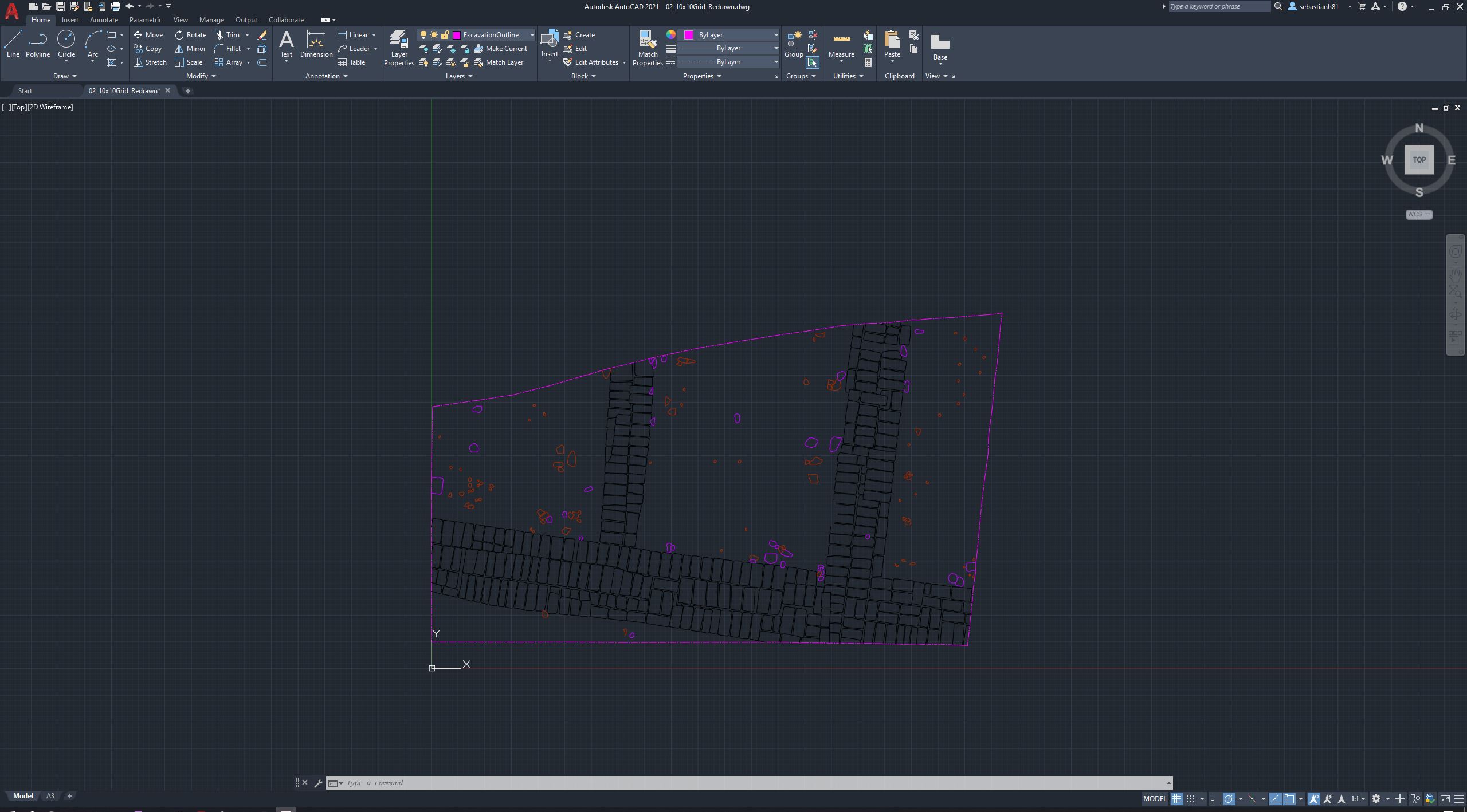
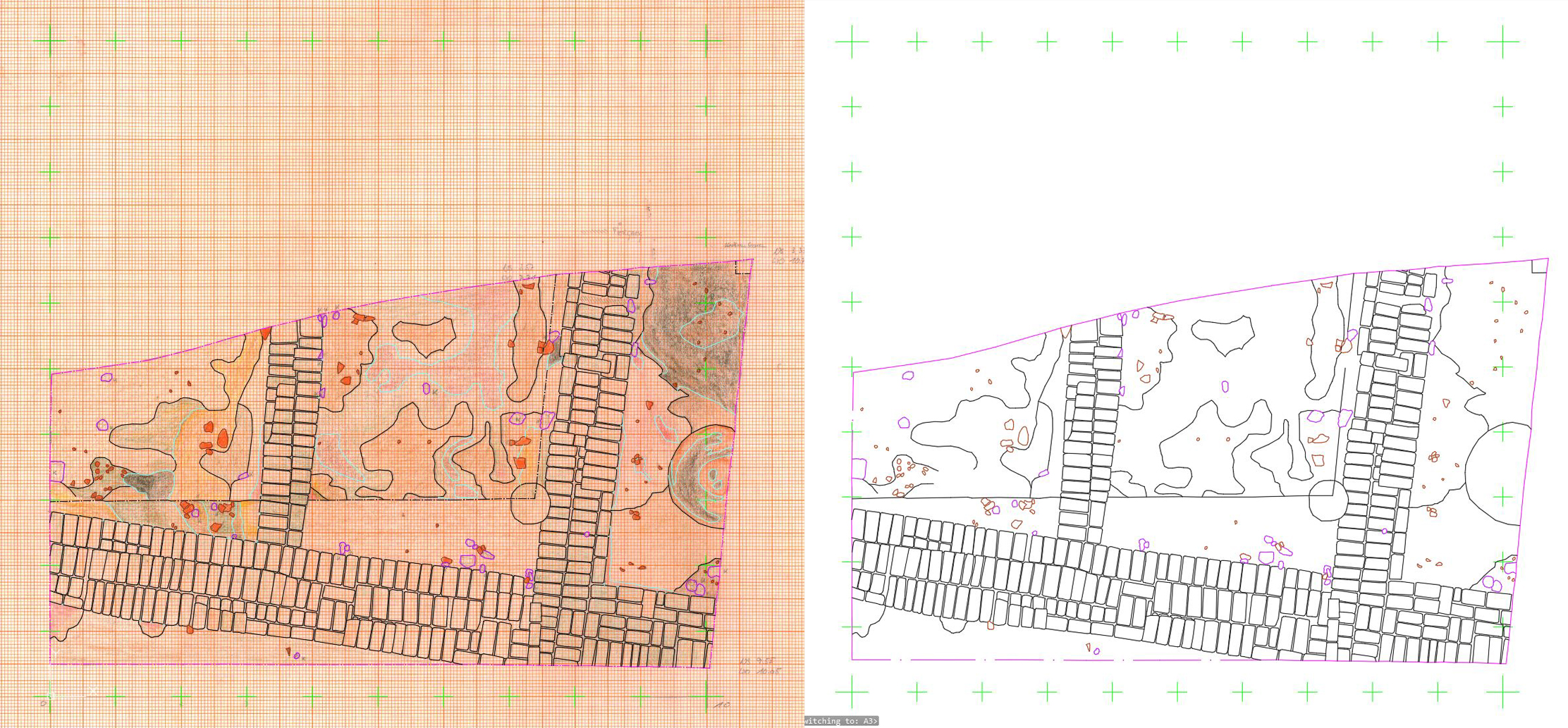
Make sure you use at least three dots on the corners of the mudbricks to give them some detail. Start redrawing all the mud bricks until you are finished. Practice, practice and practice. We still need to redraw all the other things in the drawing. The red pieces on the drawing are pottery, and the white (or transparent) pieces are stones (sometimes with a K as a signifier, which you don't need to redraw). We call the pottery layer Pottery_Outline and give it a dark red colour. We name the layer for the stones Stones_Outline and give it a purple colour. Remember to activate the layer before redrawing and make sure that each object is closed, either by completing the circle or by snapping to other lines and intersections.
When you are finished, we need to look at the soil colours. If you look closely, you'll see that some of the soil colours have a black outline and some don't. We will create a layer for the black outline as well as for the border between the soils without a line. The black outline layer is called Terrain_Outline with a black colour and we can redraw it first. The layer for the border between soil colours without a black line is called Terrain_NoPrint and we give it a light blue colour. We do not want this line to be printed, so we look in the Layer Properties in the line of the layer we just created for a small printer icon. If we click on it, this line will not be printed, which is exactly what we want. However, we still need the line to define the boundaries of these soils and we want to fill them later. We also do not want to show the line in our layout, because the layout should represent what we are going to print. To deactivate the line, we switch to our layout window, double-click inside the drawing to activate the thick border and then open the Layer Properties to click on the AF-Freeze (**AF-Frieren**) button. Deactivate the drawing by double-clicking outside the thick border.
We can now redraw all the invisible boundaries of the drawing. Draw a line between the different ground colours, making sure that each element is fully encircled in some way so that we can fill it in later. There is still some work to be done. Two lines in the drawing are a black dotted line (try to spot it). We need to create an extra layer called Terrain_Outline_DashDotted and give it a black colour. In the Layer-Properties we also change the Line Type option from Continuous to ACAD_ISO10W100 by loading it into the list that appears. We should also use this line type for our ditch line (pink).
You can now proceed to Chapter 3: Hatching and Labelling.
