Chapter 6: Boolean Operators
Anheben
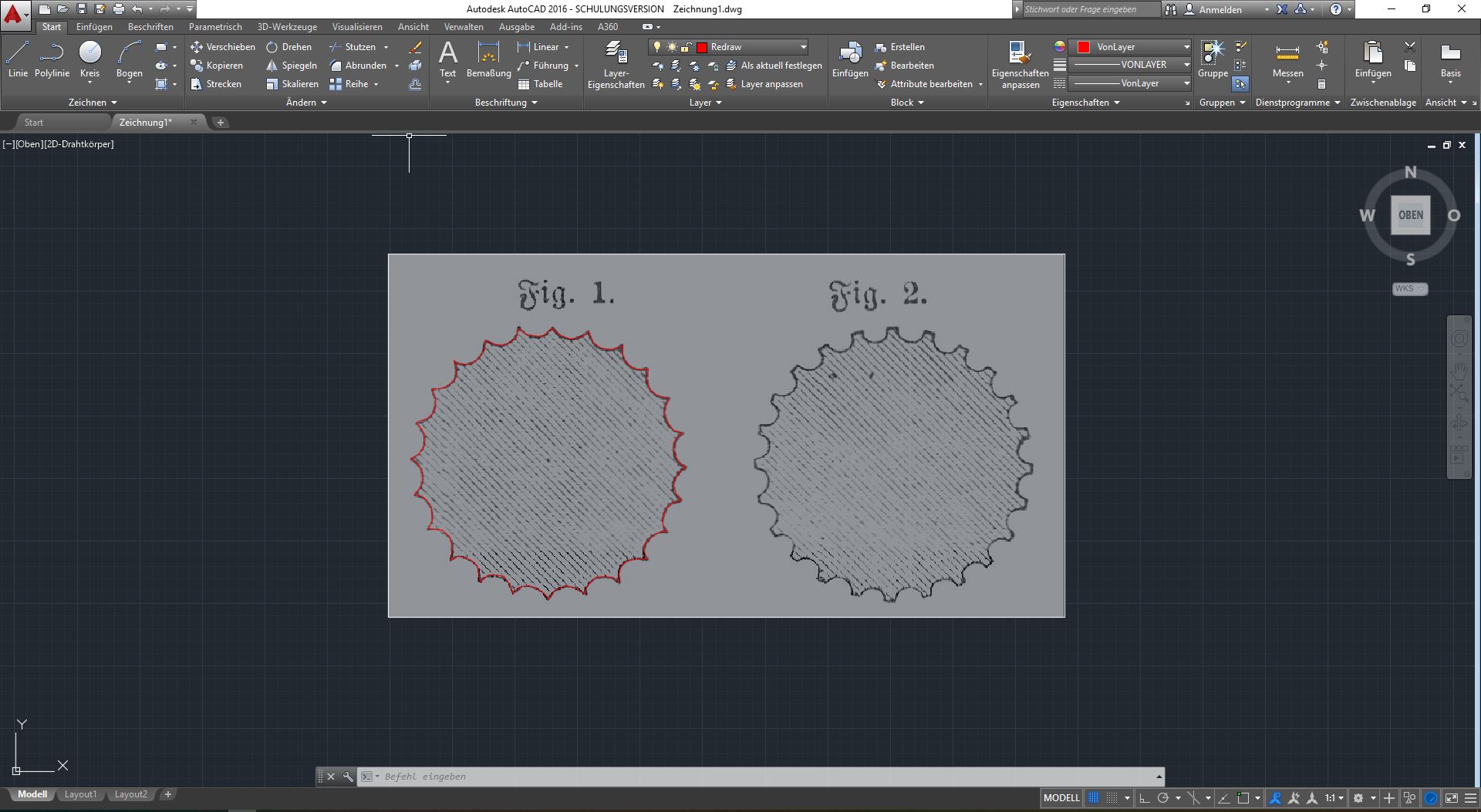
So we are now familiar with a number of tools for 3D design in ACAD. In this exercise we are going to take a closer look at all the tools we have not touched on so far. This time we will try to build our column in a different way. We will start by adding the top view of a column again, using the reference file as a reference. As discussed in Chapter 2, we'll start by redrawing the column on a different layer. If you like, you can also use the other shape on the right.
This time, instead of extruding individual barrels, we are going to create a one-piece column that becomes slightly thinner at the top. To do this, we will switch to the 3D view and copy our new shape exactly on top of the original, but at a height that seems reasonable to us. We then want to scale the top shape down a little so that we have a column that gets thinner at the top. Select your shape and use the Skalieren/Scale tool from the Start menu. ACAD wants to know the base point for scaling. If you enter 0,0,0 in the command line, you'll have a good reference point. As you move the mouse up and down, the scaled shape should come into view. As you can see, the closer you get to absolute zero, the smaller the shape becomes. Try to scale the shape down just a little, not too much.
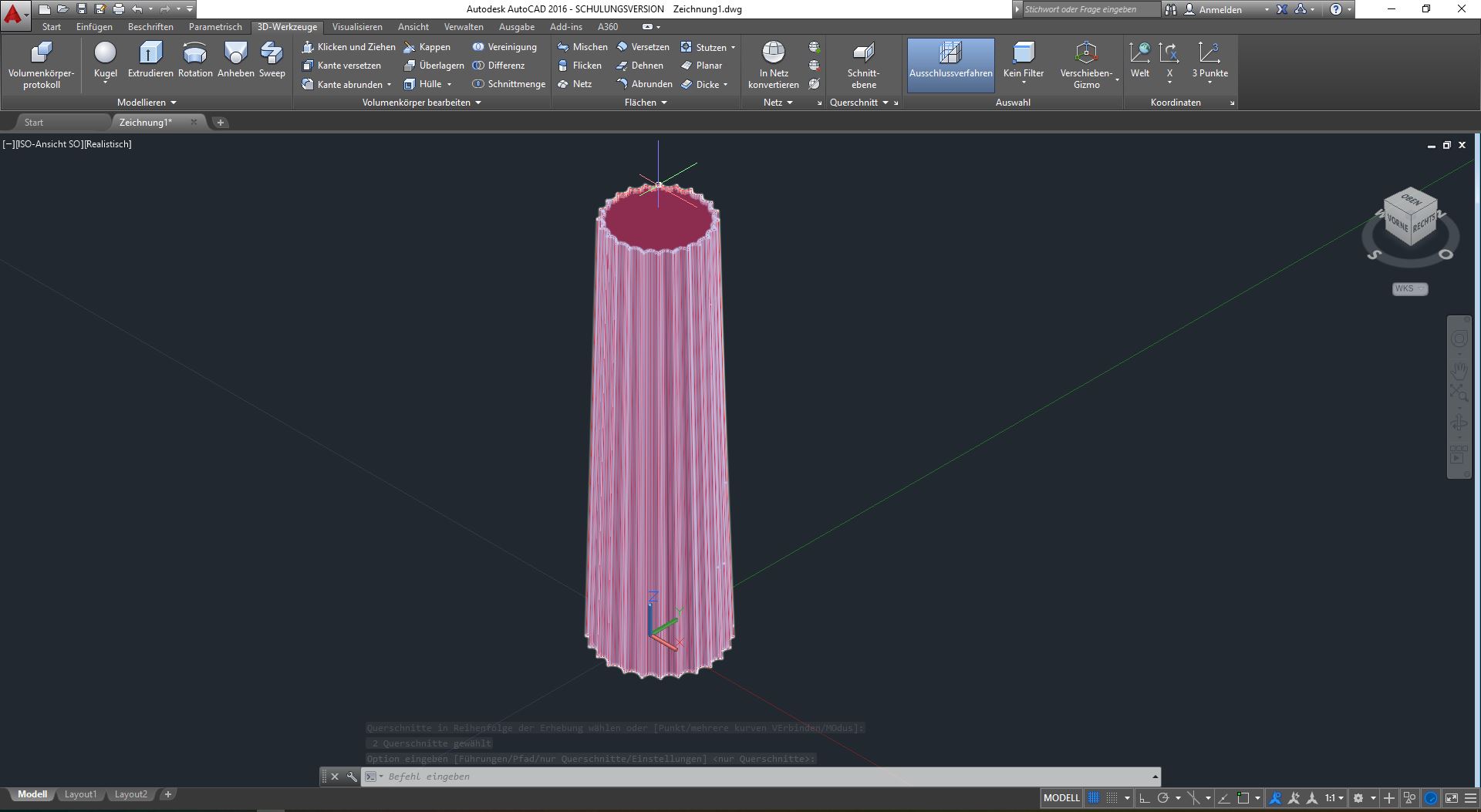
We can now try to connect these two shapes using a new tool called Anheben/Elevate. Select the tool from the 3D-Werkzeuge menu, then click on the bottom shape and then on the top shape and press Enter twice. You should see a result like the screenshot on the side. Actually, we are not done yet, so press CTRL+Z to undo your work, so that you only see the two shapes on top of each other again. We now want to use the tool to create not only the shaft of the column, but also the Echinus. To do this we need a copy and some circles.

First, make a copy of the top shape and place it slightly above the original. Then switch to top view and create a simple circle, slightly larger in diameter than the Doric column shape. This will be our Echinus base and should also be placed slightly on top of the last shape. For better understanding: The red lines are the Doric shapes and the blue lines are the circles. Now we want to copy the first circle, move it up and make it a bit bigger. We repeat this step to get the maximum diameter of the Echinus. The next copy should also be placed slightly higher, but scaled down again. The last circle should simply be a copy of the first circle and placed on top.
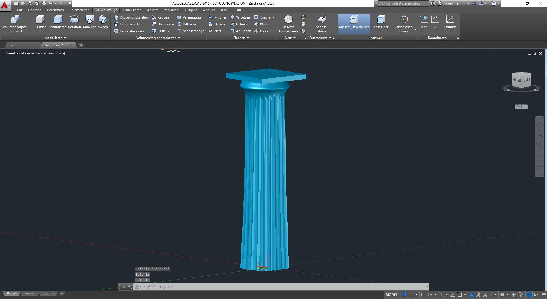
Now try using the Anheben tool again, but this time select all the shapes from bottom to top in that order and press Enter twice. Isn't that nice? If you look closely, you can clearly see the transition between the Doric shape and the circular shape, which is nice and smooth. This tool is great for something like this where you want to get a more dynamic result. Basically all you have to do is put a cube on top as an abacus and you are done.
Boolean tools
We also want to have a closer look at the Boolean Tools. Boolean Tools basically means modelling with Boolean operators: AND, OR, NOT. These operators are used in mathematics, but we can also use them in 3D modelling. In AutoCAD these operators are called Intersect (AND), Union (OR) and Subtract (NOT).

Let's have a look. If you create a box and a sphere in each of the top four corners, we can experiment with the Union and Subtract tools. Select the Union tool from the 3D Tools menu. Remember, if the 3D tools are not visible, you need to turn them on first. Also remember: The shortcut for 3D snapping in AutoCAD is the F4 key. Try to construct the spheres so that their centre is exactly in the corner of the box. After selecting the tool, you can select the objects you want to join (or combine). So select two of the spheres and the box and press Enter.
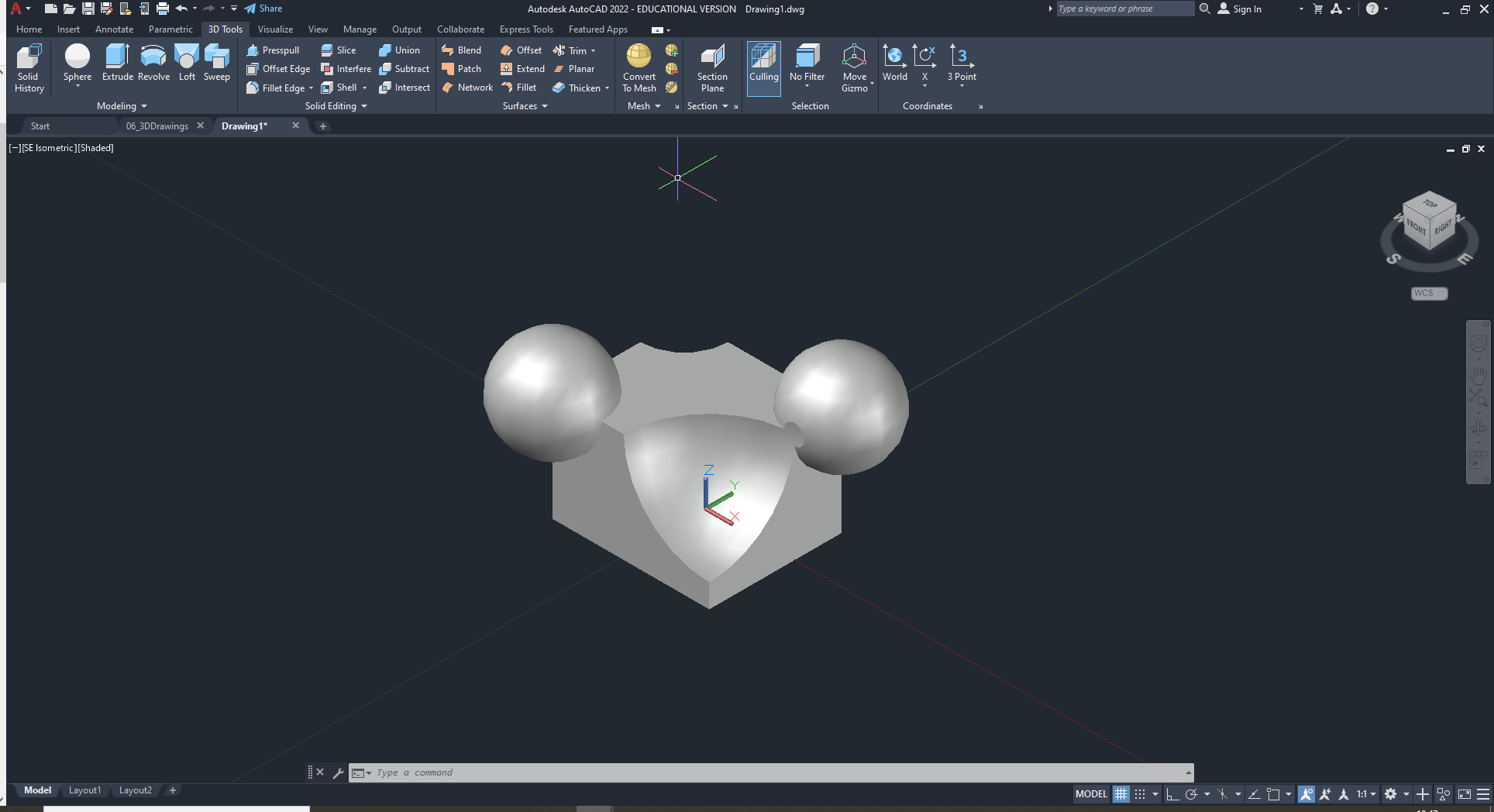
It doesn't look like much, but if you move your mouse over the object, you'll see that the box and two of the spheres are now a single object. Now let's try something else. Select the Subtract tool, then select the box (with the two spheres attached) and press Enter, then select one of the remaining loose spheres and press Enter. You can repeat the process for the other remaining sphere and your result should look something like this.
So far for the Union and Subtract tools. In the following example, we will take a look at AutoCAD's third Boolean tool.

Create a sphere and a cube. I want you to stick the cube into the sphere as shown in the screenshot on the side. So the cube should stick with one of its corners inside the sphere. Then select the Intersect tool, select both objects and press enter. You are now left with only the part of the two objects that intersected. Great, right? If you are a perfectionist, try constructing a combination of sphere and cube where the corner of the cube is exactly in the middle of the sphere...
Now these tools give us a great opportunity to step up our modelling game. Sometimes it makes sense to combine tools, sometimes it doesn't. In any case, modelling (or rather sketching) in 3D can have some valuable uses. I have said it before and I will say it again: AutoCAD is not the best 3D software out there, but it can certainly be used to sketch things in 3D or to visualise what you have already done in AutoCAD. To deepen our knowledge of AutoCAD's 3D modelling tools, there is just one last challenge: try to reconstruct the objects below and have fun!

