Chapter 3: Hatching and Labelling
Hatching
So most of the work is done, but so far all we have done is draw lines, which looks boring. We also need to fill our mud bricks, stones and various soils with colour. We also want to distinguish artefacts from soil colour, so we will use two different fill styles. We will start simple though.
Solid Filling
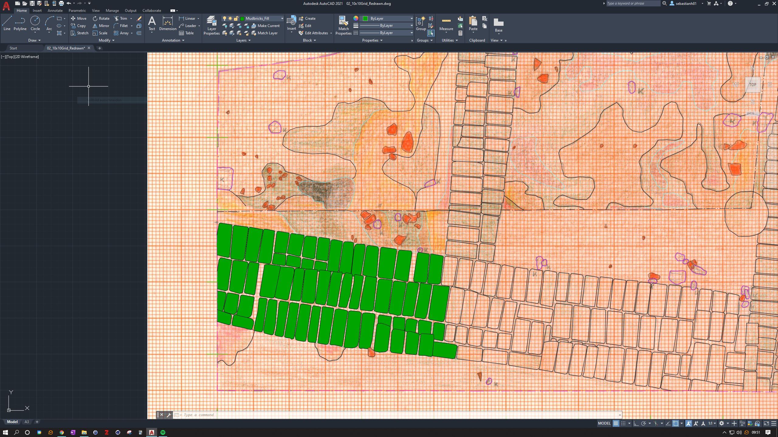
Let's start again with the mud bricks. Mudbricks are filled with a green colour. So we open the Layer-Properties (**Layer-Eigenschaften**) and create a new layer named Mudbrick_Fill and give it a green colour (92). Double click on it to make it the active layer. Back in our drawing we will look for the Hatch command. You'll find a small button in the Home toolbar, quite far to the left. It is one of the three icons to the right of the Arc command. The bottom one. Hover your mouse over it to see the info box. Click on the Hatch command and a sub-menu will appear. First select the pattern and click on Solid. Then click on Pick Points on the left. The command is now active. You can now click into one of the mud bricks and see it fill with a solid green colour. You can also click several mud bricks in a row to fill more than one mud brick. As long as your drawing is waterproof and there are no holes in the mud bricks, hatching should work well. Select 5-8 mud bricks and then press space to exit the command. If you look, you'll see that you can also select the hatch by clicking on it. The more mud bricks you select at once, the bigger the hatch will be. So here is a word of advice: Don't start clicking all the mudbricks at once to get a big mudbrick hatch. At some point you will need to make some corrections and this will probably involve deleting the hatch so that you can change or correct the line drawings. If you click on all the mudbricks at once and then delete them later, you'll have to do it all over again. My tip here: Activate the hatch command, click inside 8-10 mud bricks, exit the command by pressing space, re-enter the command by pressing space again and then fill in the next 8-10 mud bricks. Working in batches will make your life easier. Go on and fill all the mud bricks. If you click in the wrong place, simply press CTRL+Z to undo the last step.
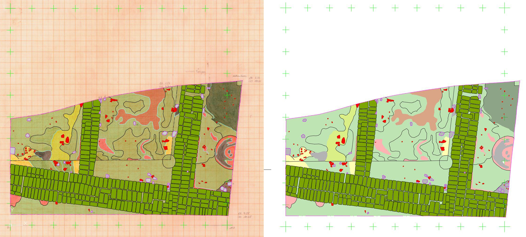
You can repeat the same process for the pottery (Pottery_Fill: red colour) and the stones (Stones_Fill: white colour). Looks good, no? Well, let's continue. We also want to fill the soil. We have four different soils on the map: ash, mud, sand and white. Anything black on the map is ash, greenish or no colour is mud, yellow is sand and red is whiting. It is sometimes difficult to see, but just try your best to identify each colour. We are going to fill this in a bit differently though. We will use the same method, but we will do the layers a little differently. Let's start with the ash fill. Create a layer named Ash-Fill and give it a black colour. However, in the Transparency column, enter a value of 70. This will make the layer semi-transparent and it will look different on paper than a solid fill. You can also create the other layers (Mud_Fill: green colour, Sand_Fill: yellow colour, Whiting_Fill: red colour) all with a transparency of 70. Then you can start filling the soil with these new layers. If you look at the layout, you'll see the difference.
Nivellements
So the next step is to add some nivellements, or levels. On a normal excavation drawing you'll see some markers for heights, but as you've probably noticed, these markers are not present in our drawing. We only see the trench, no levels. This is because the elevations were recorded on a separate sheet of transparent paper that was simply stuck over the excavation drawing. You can download the levels here: Nivellements. You can now switch off the excavation drawing in the Layer Properties and attach the new drawing to the drawing on a new layer (Niv-Drawing). Look back at Chapter 2 to see how to include an image and scale it correctly so that it is in the right place. With the nivels placed at the back of our drawing, we can proceed to add the heights. One thing though: As the original JPG is quite light (the white colour of the paper), we rarely see our cursor, which is painful. However, when you select the background image, a new menu appears at the top. There you can increase the Fade option to about 40%. This helps to see the drawing better.
To work better with the nivs, we don't really need the ground fills, as they distract us. So just turn them off in the Layer Properties. Anything with a \_Fill at the end can be turned off. Later on I will show you how to create a layer filter to make it even easier to turn off certain layers. If you zoom in, you can see the nivs drawn on the paper. As you can see, there is a small triangle pointing to the location of the measurement and a number representing the measurement. First, we will make a prototype of this so that we can copy it around our drawing. In a second step, we will adjust the actual numbers for each point.
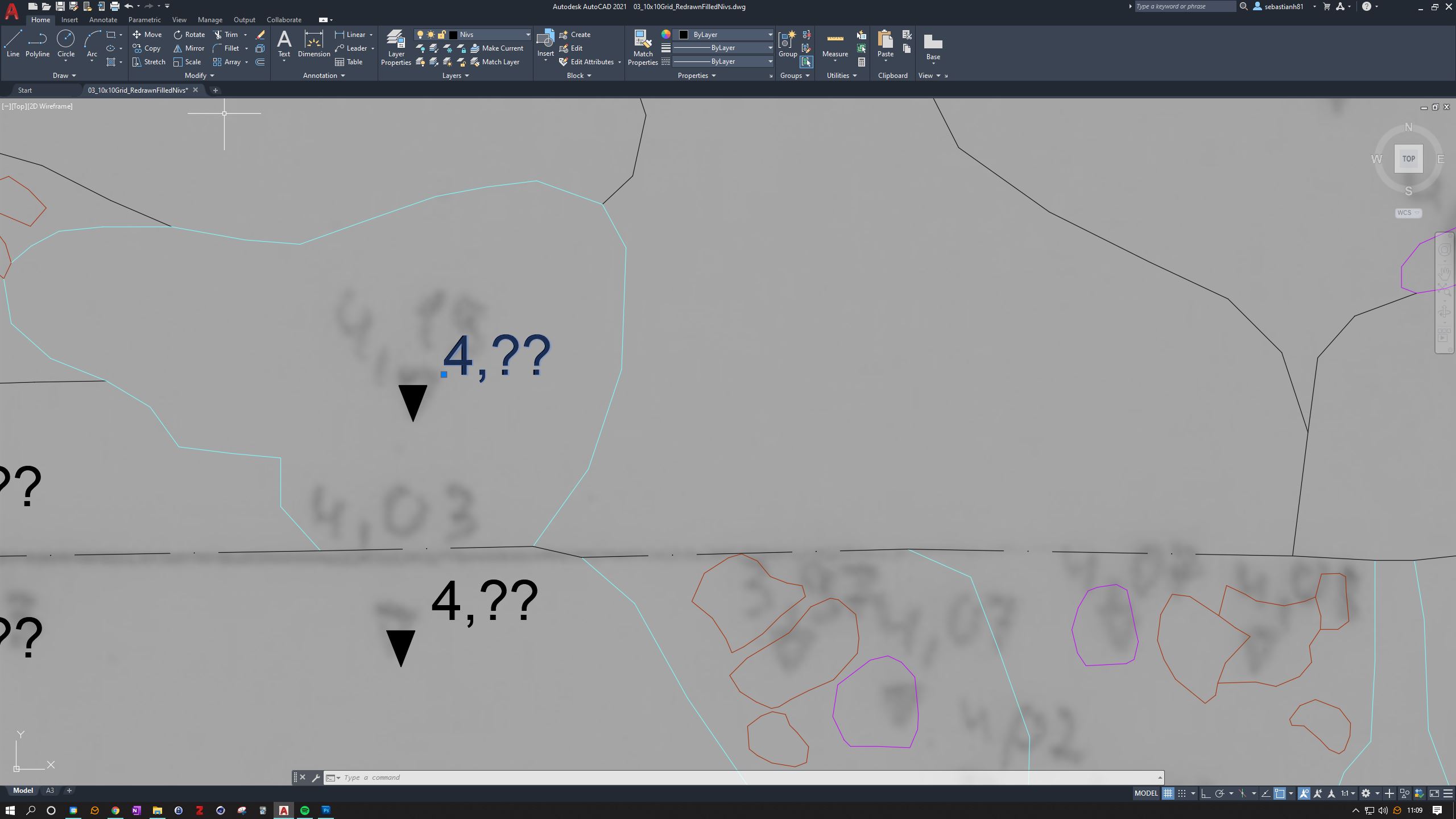
So let's start by drawing a triangle. To do this, create a new layer called Nivs and give it a black colour. Find a triangle on the drawing that you like and draw it with three points. Try to be as symmetrical as possible and make sure you close the triangle with a snap. We will then use the same layer and hatch the triangle with the same black colour. Triangle done! To create the number we will use the Text tool. You'll also find it in the Home tab of the top toolbox. Click somewhere in the drawing and type something like 4,??. As you can see, the text is way too big. To make it the right size, we'll click on the text so that it's selected, then right click somewhere to access the Properties. Under the Height or Text Height option we'll enter 5. This should be the correct size relative to our triangle. Position the text either by using the Move tool (you already know it) or by clicking on the little blue cube in the bottom left corner of the text and dragging it onto our triangle so that it sits just above and to the right of the triangle (see screenshot).
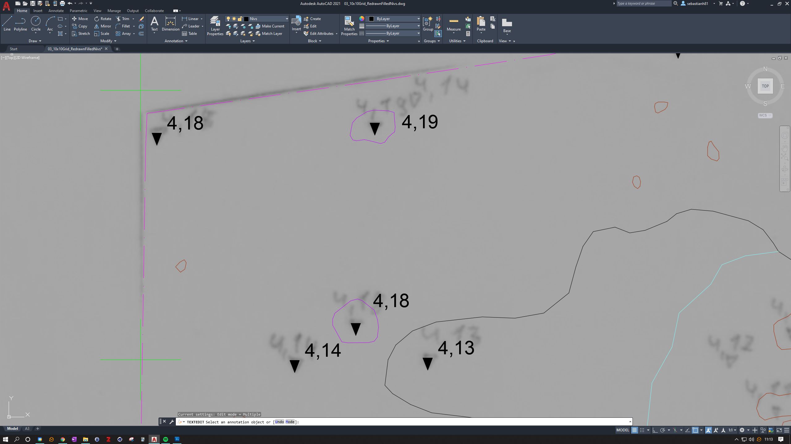
This is now our prototype group. We can select them all (triangle outline, triangle hatch and the text) and use the Copy tool to place them in the positions indicated on the drawing. When asked for a reference point for the copy, snap to the bottom point of the triangle, this way you can easily place all the prototypes in the correct positions. If you want to enter the correct numbers, simply double-click on the text and change the value! Very easy.
Labelling
Ok, on to the final chapter and the completion of our drawing. So far we have created a scaled trench (Chapter 1), redrawn all the structures and finds (Chapter 2), filled them with colour and added heights for the drawing (this chapter). We are basically done with the redrawing part of our project. If we now switch to the Layout view, we should find a perfectly digitised redraw of our hand-drawn trench.
What's missing, however, are some labels and a legend, so let's add these. Again, we are now working in the Layout view, not the drawing area, as we are finished with our drawing. So in Layout mode, try placing the drawing in a corner, I choose the top right corner. If you have not already changed the size of your paper from A4 to A3, you can do so now: Right click on the tab of your layout in the bottom left corner and start the Page Setup Manager. In the list of page setups there should be only one entry. Select it and press Change. In the new dialogue box, select the drop-down menu in the Paper Size section. Select ISO A3 (297.00 x 420.00mm). Press Ok and Close.

Once you have arranged the drawing on the paper, we can think about adding some information. First of all, we need a box that tells us what we are looking at (e.g. name of excavation, trench, date created, date redrawn, name of drawer, name of redrawer (you) and so on). First we create a new layer called Drawing_Desc and give it a black colour. Then we'll create a box in the top left corner with the Rectangle tool, which you'll find in the Home tab of the top tool menu as a small icon on the left. Click once to start the rectangle and a second time in the opposite corner to complete it. Then use the Text tool to create some text. Take a look at the screenshot for inspiration. Don't worry if you can't align everything right now, it's not important for this exercise. However, if you do want to align it, think about using a non-printable layer to create a grid on the paper so that you can snap the text boxes to it. That way you can align everything perfectly.
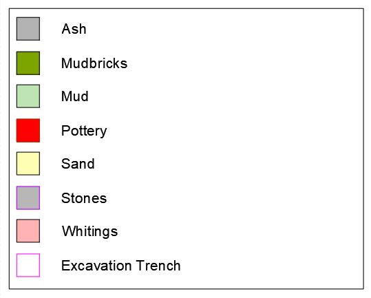
The last thing we want to do is create a legend. This is a box where we can see each colour used in our drawing and the meaning behind it. So let's start by creating a new box below the first one. Then create a new small box (see screenshot) inside it, which will represent the colour we used in our drawing. Next, create some text to convey the meaning. For example, create a black box, hatch it with the ash layer and write Ash next to it. You can then copy the whole line and just change the layers. So for the next line, we change the hatching by selecting it and choosing a different layer from the drop down menu at the top. Let's change this to Mudbrick_Fill and the text next to it to Mudbricks. The third line should be the Mud Fill and so on. Note that for Pottery you will not only change the hatching, but also the outline of the box (to Pottery_Outline). Have a look at the screenshot to get an idea of what I mean.
And you know what? You are done! Congratulations! That was a lot of work (believe me, I know), but doing it once will help you learn and also understand the time it takes to do such work. If you like, you can now print out your drawing and frame it!

